White & pink noise checks
Estimated executing time: 0,5 hours.
The noise generator is based on a 500 kHz clock generator that runs through a 31 bit shift register and generates pseudo random white and pink noise.
Preparation
Prepare the backplane in the following configuration. Stricktly follow this order:
O : Power supply
C : Noise generator
Important remark
Never ever place the noise generator RU80068-8 or detecting interface RU80068-7 in a slot intended for a filter unit. When this does happen, the output from the noise generator will be connected to the 5V DC power supply and causes undeniable damage.
Step 1 - Clock generator
Connect CH1 of an oscilloscope to IC1 pin 4:
You clearly will see the 500 kHz clock:
Step 2 - Noise output
Thereafter connect CH1 of an oscilloscope to the noise output. You can use pin P2 on the left side of the noise generator or pin N on the connector on the right side of the PCB to grab the noise signal from:
Toggle switch S1 between white and pink noise and check both outputs:
Step 3 - Noise level adjustment
The pink noise has to be slightly more amplified than the white noise, because its high frequencies have already be filtered out and so cannot contribute any further to it. P1 is used to equilise the output voltage for the white noise level.
Adjust as indicated below:
If you are not able to measure true RMS signals, turn P1 all the way up and slew back a quarter turn, that will be pretty good.
Circuit
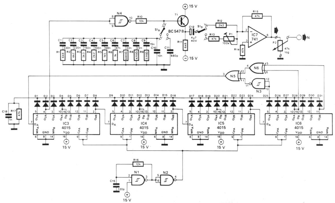
For reference and troubleshooting here is the complete noise generator circuit as published in the Dutch Elektor magazine from the early 1980’s:

Well done
Congratulations, you have now finished the input/output module adjustments, click here to navigate back to the assembly & adjustment instructions.
