Inside preparation of the 19” rack
Estimated building time: 1,0 hours.
If not already done screw down the hex standoffs in the provided places in the 3D printed backplane supports.
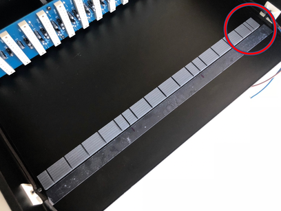
Screw down the plastic feet onto the bus print. Respect left, middle and right, otherwise the
assembly does not fit in the rack.
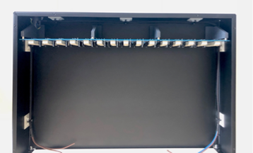
Remove the yellow protective strip from the plastic feet, aling and firmly press the bus print at about 5 cm (2 inches) from the back of the rack. Make sure the print remains parallel to the back of the case.
Test the assembly in advance because once pressed, the tape is difficult to
remove.
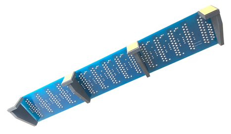
Insert
some PCB's into the back plane and press the 3D printed guides underneath.
Do not stick the guide strips yet.
Stick a temporary tape as reference aid and mark the points to align the 3D
printed PCB guides. Start in the middle and repeat this step for the left and right PCB guide.
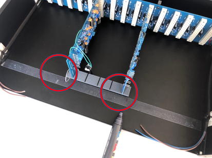
The right part has an extra notch for the power supply at the right side, so do not exchange the pieces. Remove the yellow protective strip, aling and firmly press the 3D printed guides at the marked place. Make sure the 3D printed guides remains parallel to the back of the case.
Double check the position and alignment in advance because once pressed, the
tape is difficult to remove.
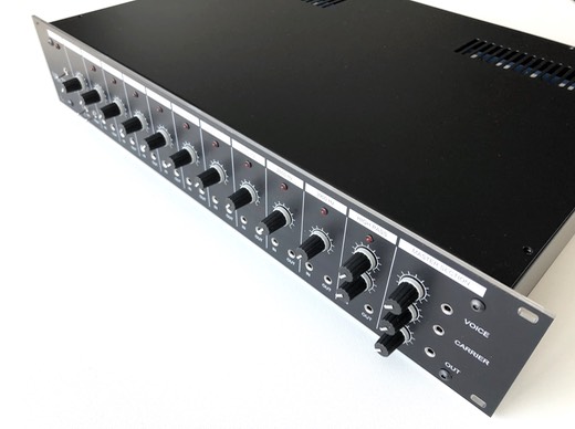
Now insert the PCB's as completed in the previous chapters into the backplane. The merged PCB's must now form a solid package:
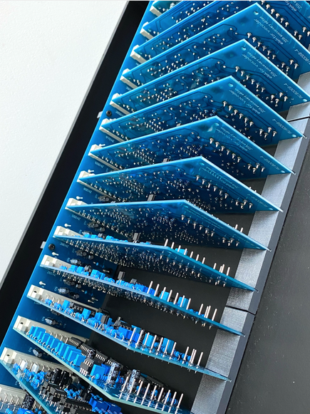
Well done
You have finished this section, so click here to navigate back to the assembly & adjustment instructions.