Introduction
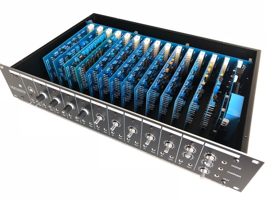
This part of the DIY vocoder building guide provides advice how to successful assemble all different parts together into one functional device and describes all necessary steps and required tools to adjust the vocoder for maximum use and pleasure.
Click here to go to the BOM section.
Step by step guide
In this chapter the following steps will be addressed:
19” rack housing cutouts
Power connection
Power supply checks
3D printed parts assembling
Front panel preparation
Input/output module adjustment
Filter adjustment
Jumper settings
Noise generator checks
Switching interface adjustment
FInal assembly
Click the above links for detailed instructions.
Important warning
A limited number of components will be connected to the mains voltage and can be dangerous if used incorrectly. It cannot be stressed enough to disconnect equipment before and servicing. Depending on local regulations, use approved connectors, wiring and insulation for the mains voltage connection.
If you are unsure do not continu and contact a professional for assistance.
