Introduction
Estimated executing time: 1 hour.
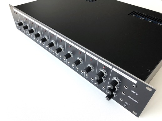
For the input/output module good signal-to-noise ratio and drive capability are extreme important. Therefore execute the following steps carefully.
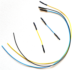
Prepare these cable sets using 1 mm solder lugs or crimp contacts to make it easier to measure the signals with an oscilloscope:
First of all temporary bridge G-H and I-J on the backplane to perform the following steps:
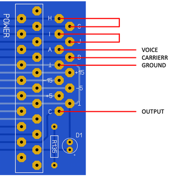
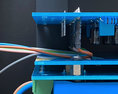
Connect 3 wires to pin A (voice), pin B (carrier) and pin C (ground).
Preparation
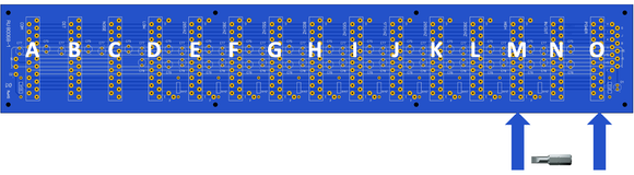
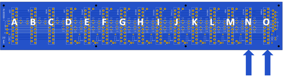
Prepare the backplane in the following configuration. Stricktly follow this order:
O : Power supply
N : Free space for adjustment trimpot
M : Input/output module (contrary to silkscreen indication on the backplane)
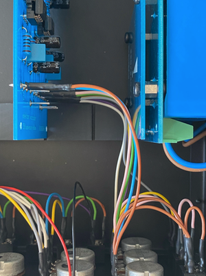
Connect the wiring between frontpanel and input/output module according to the wiring instructions you can download here. Push the contacts over the pins as far as possible, it should feel like a double click. Bend all cables for the other interfaces a bit to the left so they don’t bother you:
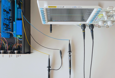
Connect an oscilloscope to pin A (voice), pin B (carrier) and ground:
Carrier input
The carrier input volume potentiometer is followed by a preamplifier with a fixed gain of approximately x10.
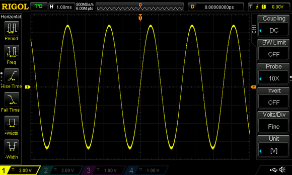
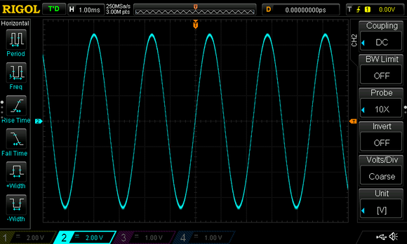
A steady waveform (sinewave 440 Hz or similar) must be connected to the line input. Turn down the speech input potentiometer and set the carrier input potentiometer to maximum. Connect CH1 of an oscilloscope to pin B (carrier).
A suitable 390 Hz sine wave can be downloaded here.
You should get the following result (peak-to-peak + 12 .. 15 V RMS). If necessary, change the input volume of the sinewave:
Speech input
The speech input volume potentiometer is followed by a preamplifier with a adjustable gain between x1 till x1000 for any input sensitivity between 7,7 mV and 7,7 V. The input impedance is 10 kOhm and in practice microphones with allmost any impedance can be used.
To use a line output as speech input apply the same 440 Hz sine wave as used for the carrier to the speech input. Turn down the carrier input potentiometer and set the speech input potentiometer to maximum.
Connect CH2 of an oscilloscope to pin A (voice). Adjust P16 until you get the following result (peak-to-peak + 12 .. 15 V RMS):
To compare both signals (voice and carrier) set the corresponding potentiometers on the frontpanel to maximum:
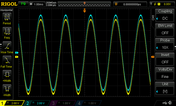
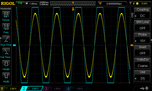
Avoid distortion at all times:
Now your speech input has been calibrated for using line levels.
Handy tip
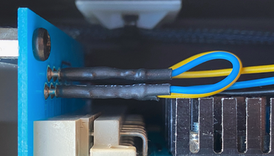
Use a small screw bit that fits on the choosen trimpots to facilitate the adjustments. Put some heat shrink over the hex holder to prevent short circuits.
Completion
Move the input/output module to the intended slot N:
If according to the instructions heat shrink is applied, bend all wires as short as possible to leave enough room for the PCB to snap into place. If necessary reheat the heatshrink to get all wires in the correct position:
Well done
Congratulations, you have now finished the input/output module adjustments, click here to navigate back to the assembly & adjustment instructions.