Swithing interface adjustment
Estimated executing time: 0,5 hours.
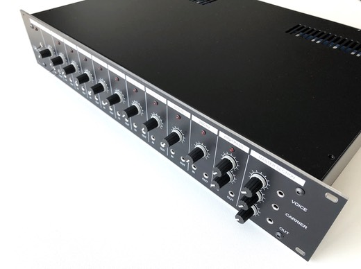
To complete this section it is assumed that the vocoder in his basic configuration has been assembled, all filters have been adjusted and the noise generator has been successfully tested.
In this section there is no need to connect all wiring to the front panel, but do not continue if any of the previous steps is not completely finished.
As there is no wiring between the filter boards and the the frontpanel yet, do not forget to temporary interconnect the output jack connection with the front panel potentiometer connection as follows:
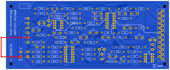
Do this for all band filters, including the low pass filter and the high pass filter. Without this temporary connection the vocoder will not produce any sound.
Preparation
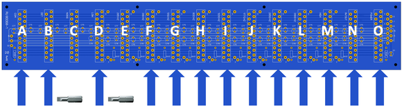
Prepare the backplane in the following configuration. Stricktly follow this order:
O : Power supply
N : Input/output module
M : High pass filter
L : Band filter 3900 Hz
K : Band filter 2650 Hz
J : Band filter 1200 Hz
I : Band filter 800 Hz
H : Band filter 390 Hz
G : Band filter 256 Hz
F : Low pass filter
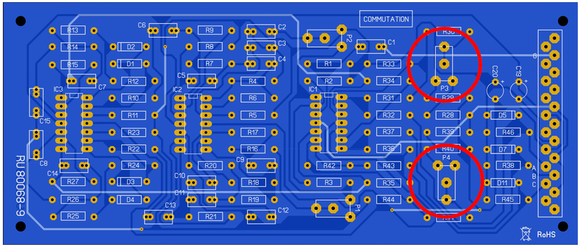
D : Commutation interface RU80068-9 (contrary to silkscreen indication on the backplane)
B : Detecting interface RU80068-7 (contrary to silkscreen indication on the backplane)
A : Noise generator RU80068-8 (contrary to silkscreen indication on the backplane)
Important remark
Never ever place the noise generator RU80068-8 or detecting interface RU80068-7 in a slot intended for a filter unit. When this does happen, the output from the noise generator will be connected to the 5V DC power supply and causes undeniable damage.
The 1770 Hz and 550 Hz bandfilters will not be used at this moment, this to free up some space to facilitate the switching interface adjustment procedure.
Handy tip
Use a small screw bit that fits on the choosen trimpots to facilitate the adjustments. Put some heat shrink over the hex holder to prevent short circuits.
Step 1 - Switching to voiced or unvoiced
Trimpots P1 and P2 preset the switch to voiced or unvoiced as required. This can be done by alternately uttering ‘A' and 'S' sounds in the microphone. Depending on the results, the sensitivity can be readjusted if necessary.
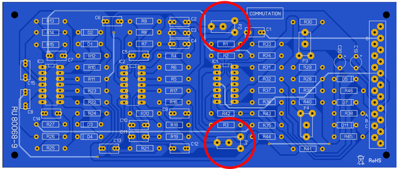
Trimpots P3 and P4 preset the trigger point of the comparators and must be adjusted simultaneously with P1 and P2.
Switch S1 acts as a select switch for the voiced state. It has been added to enable musical instruments to be used as modulators as well. Whenever music is entered at the speech input, closing the switch will prevent a sudden noise from being fed to the filters at every high tone. Whatever the signal, the detector will always decide it is voiced.
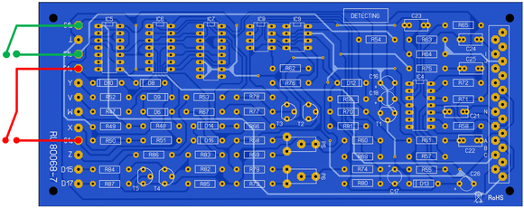
Step 2 - Calibration of the OTA's
The OTA's in the carrier/noise circuit need to be very carefully calibrated with the aid of trimpots P5 and P6. This must be achieved by a rectified signal at the control input R66 (unvoiced in) and control input R77 (voiced in) or much easier on the feeling / hearing.
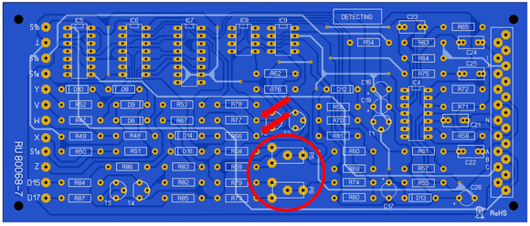
If the
unit is not properly calibrated irritating
click sounds will be produced when the
detector is switched, which happens regularly in speech and singing.
Circuits
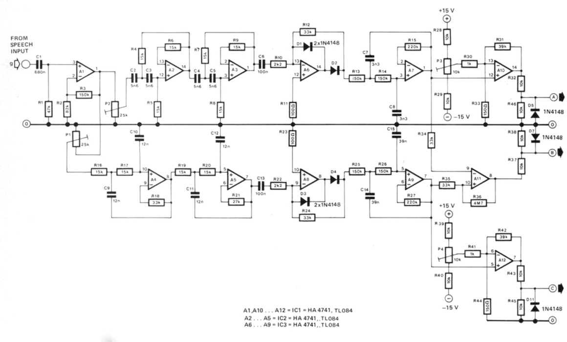
For reference and troubleshooting here is the complete voiced unvoiced detector circuit as published in the Dutch Elektor magazine from the early 1980’s:
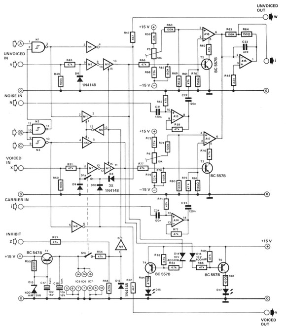
For reference and troubleshooting here is the complete voiced unvoiced switch circuit as published in the Dutch Elektor magazine from the early 1980’s:
Well done
Congratulations, you have now finished the switching interface adjustments, click here to navigate back to the assembly & adjustment instructions.