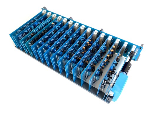
PCB reference RU80068.1
Estimated building time: 2,5 hours
To complete this step the PCB with reference RU80068.1 is required.
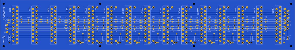
Sort
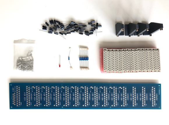
all required components as indicated in the BOM:
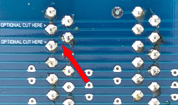
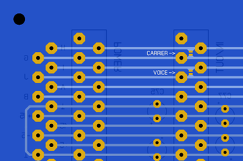
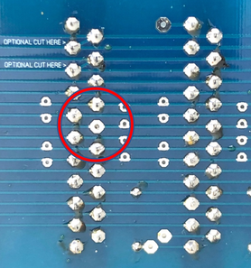
For the extended version of the vocoder (the model with the sibilance expansion) cut the connection between pin 4 & pin 5 on the solder side of the PCB. Do not cut the connection between pin 2 & pin 3.
This step is only applicable for the prototyping boards:
On the other hand for the production run boards, bridge the carrier jumper at the solder side of the PCB. Leave the voice jumper open execpt if you want to use the vocoder is the basic configuration (without the sibilance expansion).
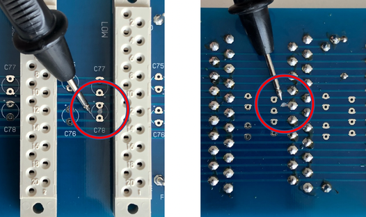
Cut the trace leaving at pin 12 left from the connector labeled LOW. Do this both on the component side as well as in the solder side from the PCB. This step is only applicable for the prototyping boards:
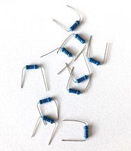
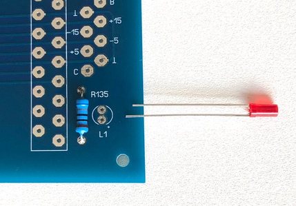
Bend
the resistors so that they fit neatly right away:
Solder
the resistors on the right position:
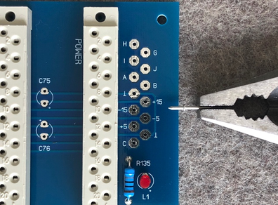
Put
the LED in its place. The long wire (anode) does correspond with the + in the
PCB:
Place one
of the connectors into the board, do not exert
any excessive force. Be
carefull not to bend the pins:
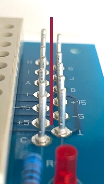
Solder
only pin 1 and pin 21 and check for a right angle:
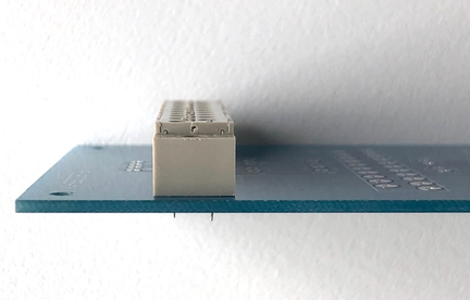
Correct
if necessary and solder all remaining pins:
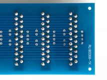
Double
check not to skip one of the soldering tabs, sometimes it's hard to see skipped
holes:
Use
a pliers to press all solder pins into the PCB. The solder pins should have a
diameter of 1 mm, the holes in the PCB have the same size. So firmly press the
pins into the right positions:
Check
if the pins are alligned, before soldering:
Insert all electrolytic
capacitors (e-caps), no
chance of mistakes as they have all the same value. Solder only 1 of both legs, this allows lining up the
components. Watch the polarity, correct if necessary and solder all remaining
legs:
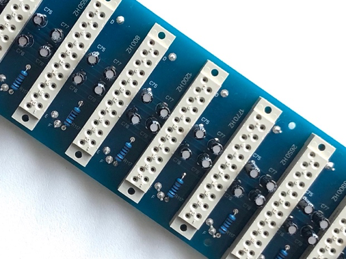
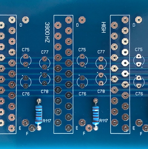
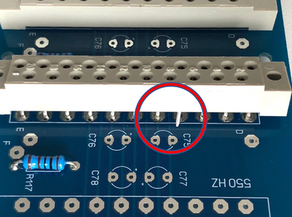
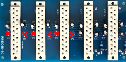
Do not
install C76 & C78 around the 3 connectors on the left, labeled COM, DET
& NOISE.
This step is only applicable for the prototyping boards:
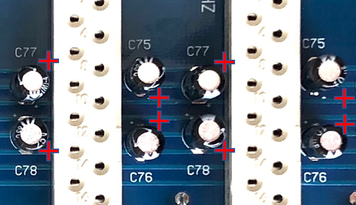
The
polarity indication on the silkscreen for C77 and C78 has been inverted, so do not use this indication as reference but rely on the picture below.
This step is only
applicable for the prototyping boards:
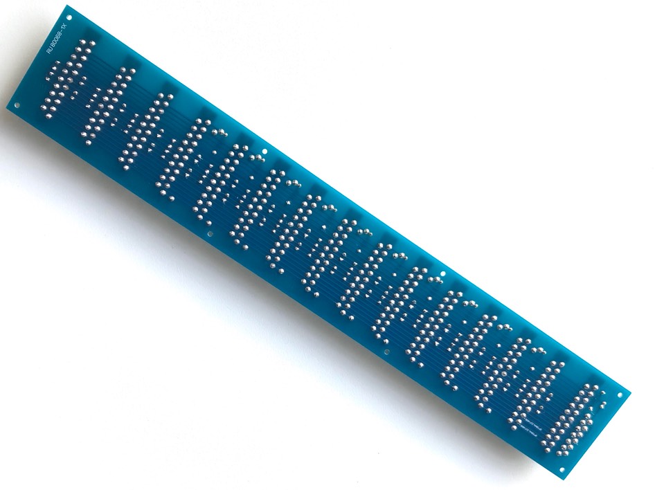
Thoroughly clean the PCB using flux cleaner and check for bad soldering or tin bulbs:
Well done
Congratulations, you have finished the back plane section, click here to navigate back to the building guide.