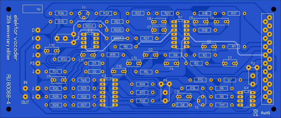
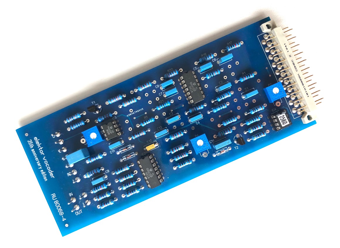
PCB reference RU80068.4
Estimated building time: 1,5 hours per filter
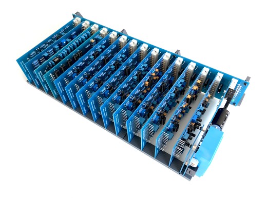
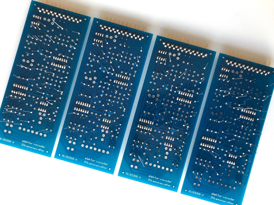
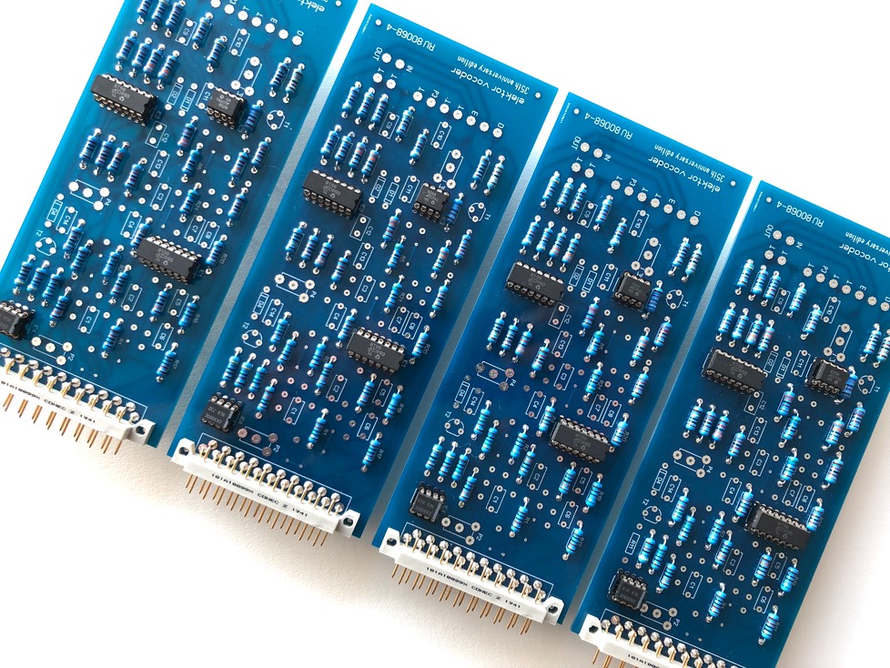
To complete this step the PCB with reference RU80068.4 is required in 8 copies.
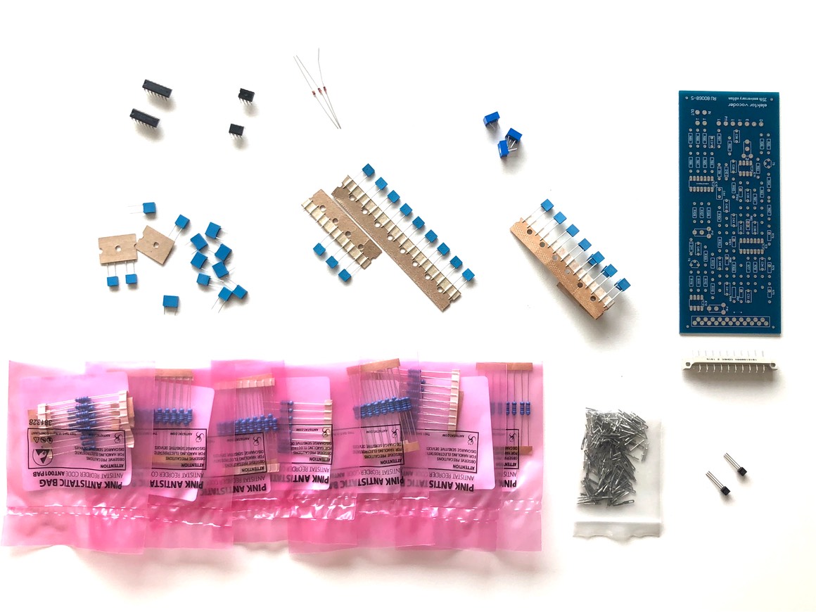
Sort all required components as indicated in the BOM:
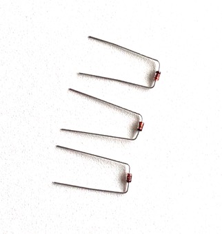
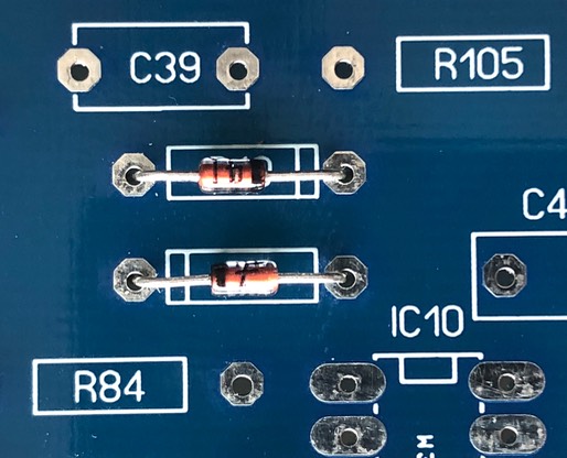
Bend the diodes so that they fit neatly right away:
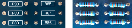
Bend the resistors so that they fit neatly right away:

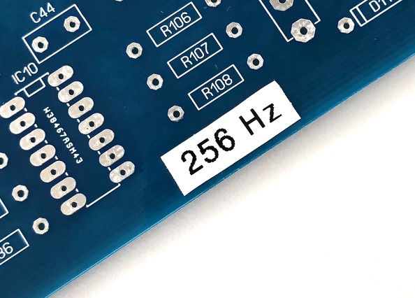
Label the 8 band pass filter PCB’s with their own frequency, this in order to prevent errors afterwards.
Solder the diodes on the right position. Note the direction of the black line (component) and tabbed indication (silkscreen). Do not reverse the polarity of these components.
Solder the resistors on the right position:
Put the 21 pin connector to the board, do not exert any excessive force:
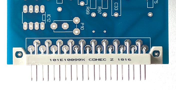
Solder only pin 1 and pin 21 and check for a right angle. Correct if necessary and solder all remaining pins.
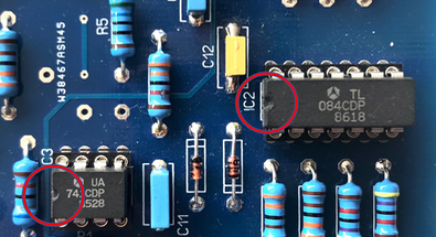
Add also the IC sockets by soldering only 1 pin. Check the direction and alignment of the IC sockets before soldering the remaining pins.
Plug the corresponding IC's into the IC sockets, double check the direction of the notch to avoid destroyed IC's afterwards.
Insert both transistors, do not mix the BC547 and BC548, they look exactly the same.
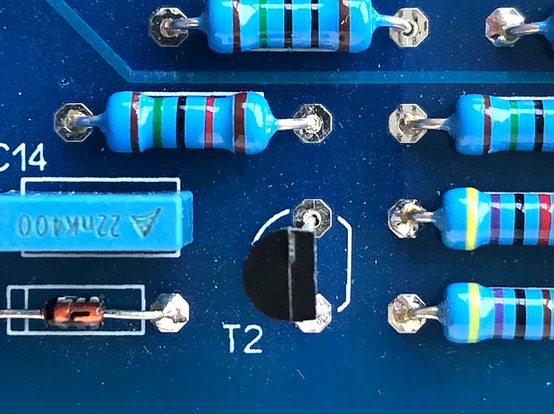
Solder only 1 of the legs, this allows lining up the components. Watch the direction of the transistor, correct if necessary and solder the remaining legs.
Thereafter add the trimpots for tuning and adjustment of the filter later.

Label the 8 band pass filter PCB’s with their own frequency , this in order to prevent errors afterwards.
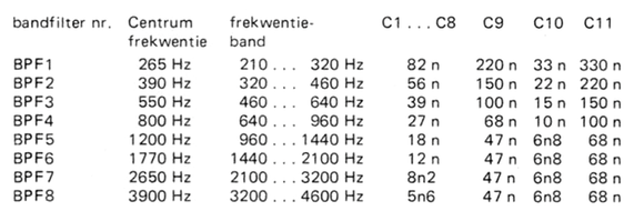
Add the film capacitors as specified in the list below:
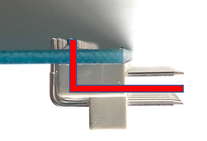
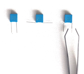
Only applicable for prototyping boards and depending on the choosen components, bend the capacitor legs as illustrated to adapt the lead spacing:
Finally use a pliers to press all solder pins into the PCB. The solder pins should have a diameter of 1 mm, the holes in the PCB have the same size. So firmly press the pins into the right position.
Thoroughly clean the PCB using flux cleaner and check for bad soldering or tin bulbs:
Some more to go
Repeat the above steps to build all 8 band filters. Consecutively you need to complete the following band filters:
256 Hz
390 Hz
550 Hz
800 Hz
1200 Hz
1770 Hz
2650 Hz
3900 Hz
Important remark
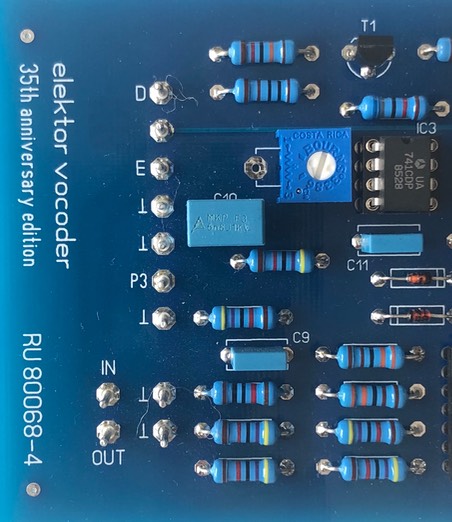
If the component ordering was based on the initial BOM (23/09/2018 or 07/11/2018), trimmer P1 had a value of 100 kOhm. Together with the 180 kOhm resistors R200 and R201 this provides a bias control range of -4 .. +4 V on the inverting input of the LM741 opamp. In practice this seems a bit too much to fine-tune the offset in an easy way. The result is that (in case of an inaccurate setting of P1) the opamp immediately saturates.
If the updated BOM (11/02/2019 or later) was used to order all componentns, ignore these instruction, as the correct trimmers are already included.
The hard way is to trim P1 until you measure approximately 0.0 mV on pin 6 of IC3. But there are 3 much simpler solutions to refine this adjustment. Based on your desoldering skills, choose one at your own choice.
Solution 1:
Replace the 100 kOhm potentiometer P1 on all filter boards by a 10 kOhm equivalent.
In this solution 8 trimmers should be replaced, 1 on each band pass filter.
Solution 2:
Replace both resistors R200 and R201 on all band filter boards by a 1 MOhm 1% equivalent.
In this solution 16 resistors should be replaced, 2 on each band pass filter.
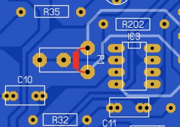
Solution 3:
Solder an additional 1/8 Watt 12 kOhm resistor over the 100 kOhm trimmer (solder side).
In this solution no desoldering skills are required.
Well done
Congratulations, you have finished the band pass filter section, click here to navigate back to the building guide.