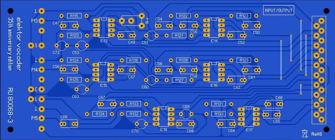
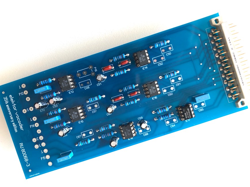
PCB reference RU80068.3
Estimated building time: 1,5 hours
To complete this step the PCB with reference RU80068.3 is required.

Sort
all required components as indicated in the BOM:
Bend
the resistors so that they fit neatly right away:
Solder
the resistors on the right position.
Add also the IC sockets by soldering only 1 pin. Check the direction and alignment of the IC sockets before soldering the remaining pins.
Put the 21 pin connector to the board, do not exert any excessive force:
Solder only pin 1 and pin 21 and check for a right angle.
Correct if necessary and solder all remaining pins:
Insert the electrolytic
capacitors (e-caps), do not
mix the 10 uF and 22 uF, they look exactly the same.
Solder only 1 of both legs, this allows
lining up the components. Watch the polarity, correct if necessary and solder
all remaining legs:
Thereafter add
the trimpot for the microphone preamp:
Add the
film capacitors:
Only applicable for prototyping
boards and depending on
the choosen components, bend the capacitor legs as illustrated to adapt the
lead spacing:
Also plug the corresponding IC's into the IC sockets, double check the direction of the notch to avoid destroyed IC's afterwards:
Finally use a pliers to press all solder pins into the PCB. The solder pins should have a diameter of 1 mm, the holes in the PCB have the same size. So firmly press the pins into the right positions:
Thoroughly clean the PCB using flux cleaner and check for bad soldering or tin bulbs:

Well done
Congratulations, you have finished the input/output module section, click here to navigate back to the building guide.
