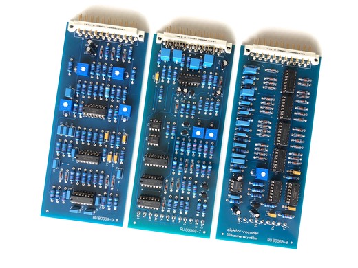
PCB reference RU80068.9
Estimated building time: 1,5 hours
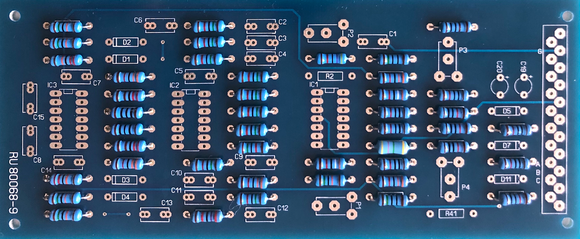
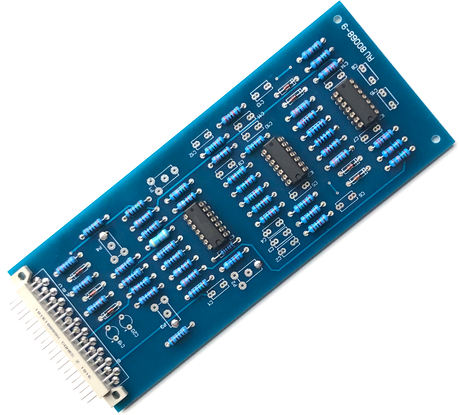
To complete this step the PCB with reference RU80068.9 is required:
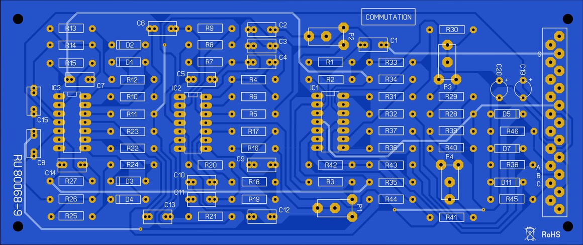
Sort all required components as indicated in the BOM.
Before soldering any component, a modification on the commutation interface PCB is required. The trace as indicated in red on the component side of the PCB should be corrected. These steps is only applicable for the prototyping boards:
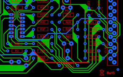
Cut
the track below R44. This step is only
applicable for the prototyping boards:

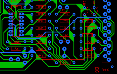
A new connection should be made. Therefore drill a small hole and connect the cutted trace from the component side to the solder side by adding a so called ' via’. This step is only applicable for the prototyping boards:
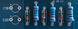
Bend the resistors so that they fit neatly right away and solder them on the right position:
Bend the diodes so that they fit neatly right away. Do not mix the 1N4148 standard diode with the 3 zener diodes as they look allmost the same:
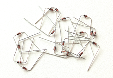
Solder the diodes on the right position. Note the direction of the black line (component) and tabbed indication (silkscreen). Do not reverse the polarity of these components:
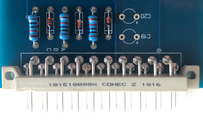
Put the 21 pin connector to the board, do not exert any excessive force. Solder only pin 1 and pin 21 and check for a right angle. Correct if necessary and solder all remaining pins:
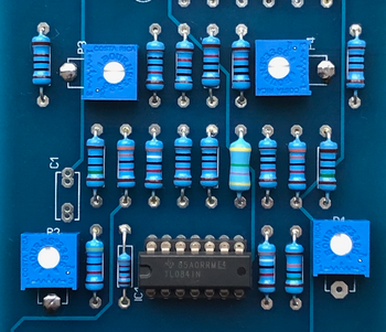
Add the IC sockets by soldering only 1 pin. Check the direction and alignment of the IC sockets before soldering the remaining pins. Also plug the corresponding IC's into the IC sockets, double check the direction of the notch to avoid destroyed ICs afterwards.
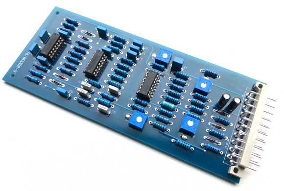
This is how the detecting interface looks now:
Add the trimpots according to the BOM:
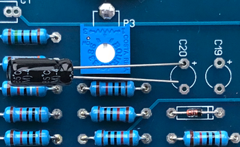
Insert the electrolytic capacitors (e-caps), check the values according to the BOM. Solder only 1 of both legs, this allows lining up the components. Watch the polarity (the long wire is the positive), correct if necessary and solder all remaining legs:
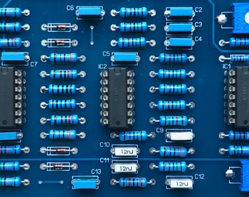
Add the film capacitors as specified in the BOM. Solder only 1 of both legs, this allows lining up the components. Crrect if necessary and solder all remaining legs:
Thoroughly clean the PCB using flux cleaner and check for bad soldering or tin bulbs:
Well done
Congratulations, you have finished the switching module, click here to navigate back to the building guide.